Showing posts with label Reviews. Show all posts

Sunday, March 27, 2011

555 Timer IC Working Principle

Block Diagram of 555 timer IC:

Comparator 1 has a threshold input (pin 6) and a control input (pin 5). In most applications, the control input is not used, so that the control voltage equals +2/3 VCC. Output of this comparator is applied to set (S) input of the flip-flop. Whenever the threshold voltage exceeds the control voltage, comparator 1 will set the flip-flop and its output is high. A high output from the flip-flop saturates the discharge transistor and discharge the capacitor connected externally to pin 7. The complementary signal out of the flip-flop goes to pin 3, the output. The output available at pin 3 is low. These conditions will prevail until comparator 2 triggers the flip-flop. Even if the voltage at the threshold input falls below 2/3 VCC, that is comparator 1 cannot cause the flip-flop to change again. It means that the comparator 1 can only force the flip-flop’s output high.
To change the output of flip-flop to low, the voltage at the trigger input must fall below + 1/3 Vcc. When this occurs, comparator 2 triggers the flip-flop, forcing its output low. The low output from the flip-flop turns the discharge transistor off and forces the power amplifier to output a high. These conditions will continue independent of the voltage on the trigger input. Comparator 2 can only cause the flip-flop to output low.
From the above discussion it is concluded that for the having low output from the timer 555, the voltage on the threshold input must exceed the control voltage or + 2/3 VCC. They also turn the discharge transistor on. To force the output from the timer high, the voltage on the trigger input must drop below +1/3 VCC. This also turns the discharge transistor off.
A voltage may be applied to the control input to change the levels at which the switching occurs. When not in use, a 0.01 nano Farad capacitor should be connected between pin 5 and ground to prevent noise coupled onto this pin from causing false triggering.
Connecting the reset (pin 4) to a logic low will place a high on the output of flip-flop. The discharge transistor will go on and the power amplifier will output a low. This condition will continue until reset is taken high. This allows synchronization or resetting of the circuit’s operation. When not in use, reset should be tied to +VCC.

Friday, December 31, 2010

Eclipse for SDCC

Although I use MIDE-51 as a major IDE, I still seek for the best (free) IDE for developing
 Microcontroller Programming. The combination of Eclipse, CDT and SDCC is an alternation tools for 8051 Microcontroller C Programming.

Eclipse is an open source community whose projects are focused on building an open development platform comprised of extensible frameworks, tools and runtimes for building, deploying and managing software across the lifecycle. Eclipse is used for Enterprise Development, Embedded and Device Development, Rich Client Platform, Application Frameworks and Language IDE.

The CDT is Eclipse's C/C++ Development Tooling project. It is an industrial strength C/C++ IDE that also serves as a platform for others to provide value added tooling for C/C++ developers.
The eclipseSDCC project aims to provide full support for the open source Small Device C Compiler (SDCC) from within the eclipse/CDT development environment. This allows embedded 'C' applications for 8051 and Z80 devices to be developed using the fully featured eclipse IDE. EclipseSDCC supports CDT managed make projects. In managed make projects CDT manages the build process by creating and maintaining the underlaying makefiles. CDT keeps track of source dependencies and can automatically rebuild the target when needed.
To install (for Windows)
  1. It requires Java Runtime Environment (JRE), I download only JRE not SDK and install it.
  2. Downlaod Eclipse SDK 3.2.1 for Windows (120 MB) and extract it to c:/eclipse. In the directory it contains eclipse.exe which is an executable.
  3. Download CDT 3.1.1 (September 29, 2006) and extract it c:/eclipse, this will prompt to replace plugins and features directory.
  4. If you have already installed SDCC for Window, skip this step. If you have no SDCC installed, read this first.
  5. Download eclipseSDCC-1.0.0, when you extract the file, it contains plugins and features directory. Copy the two direct to c:\eclipse.
Now the installation have been completed and you can find its manual in c:/eclipse/plugins/net.sourceforge.eclipsesdcc_1.0.0/help/index.html.

Eclipse for SDCC is quite large when compared it MIDE-51. However, you can manage project in Eclipse whereas MIDE-51 still have no this feature in the present version. Here is a screen shot, you should see this dialog.

Related Links

Philips P89V51RD2 Microcontroller

I am using Philips P89V51RD2 as 8051 Microcontroller Unit (MCU). And I have been developing my code with Opensouce C Compiler SDCC. Please visit my Tools pagefor software preparation guides.
The P89V51RD2 is a 80C51 microcontroller with 64 kB Flash and 1024 bytes of data RAM. A key feature of the P89V51RD2 is its X2 mode option. The design engineer can choose to run the application with the conventional 80C51 clock rate (12 clocks per machine cycle) or select the X2 mode (6 clocks per machine cycle) to achieve twice the throughput at the same clock frequency. Another way to benefit from this feature is to keep the same performance by reducing the clock frequency by half, thus dramatically reducing the EMI.

The Flash program memory supports both parallel programming and in serial In-System Programming (ISP). Parallel programming mode offers gang-programming at high speed, reducing programming costs and time to market. ISP allows a device to be reprogrammed in the end product under software control. The capability to field/update the application firmware makes a wide range of applications possible.

The P89V51RD2 is also In-Application Programmable (IAP), allowing the Flash program memory to be reconfigured even while the application is running.

Features
  • 80C51 Central Processing Unit
  • 5 V Operating voltage from 0 MHz to 40 MHz
  • 64 kB of on-chip Flash user code memory with ISP (In-System Programming) and IAP (In-Application Programming)
  • Supports 12-clock (default) or 6-clock mode selection via software or ISP
  • SPI (Serial Peripheral Interface) and enhanced UART
  • PCA (Programmable Counter Array) with PWM and Capture/Compare functions
  • Four 8-bit I/O ports with three high-current Port 1 pins (16 mA each)
  • Three 16-bit timers/counters
  • Programmable watchdog timer
  • Eight interrupt sources with four priority levels
  • Second DPTR register
  • Low EMI mode (ALE inhibit)
  • TTL- and CMOS-compatible logic levels
  • Brown-out detection
  • Low power modes
    o Power-down mode with external interrupt wake-up
    o Idle mode
  • DIP40 packages

Related LinksProduct Page: http://www.semiconductors.philips.com/
Data Sheet: P89V51RB2_RC2_RD2-03.pdf
Boot Loader: p89v_lv51rd2_bl_upd_v5.zip
FlashMagic ISP Software: http://www.esacademy.com/

A Real-Time Operating System (RTOS) for the 8051

A real-time operating system (RTOS) is a class of operating system intended forreal-time applications, including embedded systems (programmable thermostats, household appliance controllers, mobile telephones), industrial robots, spacecraft, industrial control (see SCADA), and scientific research equipment [wikipedia]. It is an advance topic in Microcontroller and Embedded Systems.

FreeRTOS.orgTM is a portable, open source, mini Real Time Kernel - a free to download RTOS. It have been ported to support several microcontroller architectures - ARM7, ARM CORTEX M3, 8051, AVR (MegaAVR), x86, PIC18, PIC24, dsPIC, HCS12, H8S, RDC, ColdFire. FreeRTOS is licensed under a modified GPL and can be used in commercial applications under this license.

For the 8051, this RTOS have been ported to Cygnal (Silicon Labs) 8051. This is the starting point for anyone who would like to study the Operating System and Embedded Design on 8051. The Cygnal port was developed on a C8051F120-TBprototyping board fitted with a 8051F120 microcontroller. The freeware SDCCcompiler was used along with the Cygnal IDE.

Building and executing the RTOS demo application

After downloads the freeRTOS source file (.exe or .zip), I extract the file to C:\FreeRTOS. The demo application for Cygnal 8051 is located in C:\FreeRTOS\Demo\Cygnal. To compiler this demo, it is require SDCC (see how to install) and GNU make. For Gnu make, I download UnxUtils.zip then extract it to C:\UnxUtils and finally edit PATH to C:\UnxUtils\usr\local\wbin (see how to edit PATH on 2000 and XP). In DOS Command Shell, change directory (cd) to C:\FreeRTOS\Demo\Cygnal and type make, the final product is main.ihx which the demo real time application for Cygnal 8051. However. the size of this file is quiet big, 72k. I have succeed compiling with SDCC 2.5.x but failed for SDCC 2.6.x.

In the conclusion, The demo application of the opensource freeRTOS have been ported to Cygnal 8051 which contains the demonstration source code. This is an avenue to learn the Real Time Operating System for the others 8051 chip.

Servo Motor Control

Servos

Servos are DC motors with built in gearing and feedback control loop circuitry. And no motor drivers required. They are extremely popular with robot, RC plane, and RC boat builders. Most servo motors can rotate about 90 to 180 degrees. Some rotate through a full 360 degrees or more.

However, servos are unable to continually rotate, meaning they can't be used for driving wheels, unless they are modified (how to modify), but their precision positioning makes them ideal for robot legs and arms, rack and pinion steering, and sensor scanners to name a few. Since servos are fully self contained, the velocity and angle control loops are very easy to impliment, while prices remain very affordable. To use a servo, simply connect the black wire to ground, the red to a 4.8-6V source, and the yellow/white wire to a signal generator (such as from your microcontroller). Vary the square wave pulse width from 1-2 ms and your servo is now position/velocity controlled.


PWM
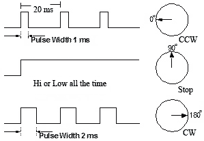
Pulse width modulation (PWM) is a powerful technique for controlling analog circuits with a processor's digital outputs. PWM is employed in a wide variety of applications, ranging from measurement and communications to power control and conversion. The general concept is to simply send an ordinary logic square wave to your servo at a specific wave length, and your servo goes to a particular angle (or velocity if your servo is modified). The wavelength directly maps to servo angle.The standard time vs angle is represented in this chart:
Figure: Pulse for controlling a Servo motor


Programmable Counter Array (PCA)
The PCA is a special modules in Philips P89V51RD2 which includes a special 16-bit Timer that has five 16-bit capture/compare modules associated with it. Each of the modules can be programmed to operate in one of four modes: rising and/or falling edge capture, software timer, high-speed output, or pulse width modulator. Each module has a pin associated with it in port 1.
Module 0 is connected to P1.3 (CEX0), module 1 to P1.4 (CEX1), etc. Registers CH and CL contain current value of the free running up counting 16-bit PCA timer. The PCA timer is a common time base for all five modules and can be programmed to run at: 1/6 the oscillator frequency, 1/2 the oscillator frequency, the Timer 0 overflow, or the input on the ECI pin (P1.2). The timer count source is determined from the CPS1 and CPS0 bits in the CMOD SFR.

In the CMOD SFR there are three additional bits associated with the PCA. They are CIDL which allows the PCA to stop during idle mode, WDTE which enables or disables the Watchdog function on module 4, and ECF which when set causes an interrupt and the PCA overflow flag CF (in the CCON SFR) to be set when the PCA timer overflows. The Watchdog timer function is implemented in module 4 of PCA. Here, we are interested only PWM mode.

8051 Pulse width modulator mode
All of the PCA modules can be used as PWM outputs. Output frequency depends on the source for the PCA timer. All of the modules will have the same frequency of output because they all share one and only PCA timer. The duty cycle of each module is independently variable using the module's capture register CCAPnL.When the value of the PCA CL SFR is less than the value in the module's CCAPnL SFR the output will be low, when it is equal to or greater than the output will be high. When CL overflows from FF to 00, CCAPnL is reloaded with the value in CCAPnH. this allows updating the PWM without glitches. The PWM and ECOM bits in the module's CCAPMn register must be set to enable the PWM mode. For more details see P89V51RD2 datasheet.
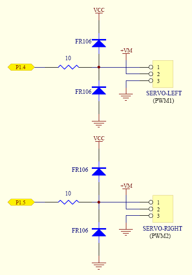
This is an example how to control servos with 8051 by using PWM. The schematic is shown below. I use P1.4 (CEX1) to control the left servo and P1.2 (CEX2) to control the right servo. Here, I use GWS servo motor model S03T STD. I need three states of duty cycle:
  • 20 ms to Stop the servo
  • 1 ms to Rotate Clockwise
  • 2 ms to Rotate Counter-clockwise

Calculation for duty cycle (for XTAL 18.432 MHz with 6 Clock/Machine cycle)
  • Initial PWM Period = 20mS (18.432MHz /6-Cycle Mode)
  • Initial PCA Count From Timer0 Overflow
  • 1 Cycle of Timer0 = (1/18.432MHz)x6 = 0.326 uS
  • Timer0 AutoReload = 240 Cycle = 78.125 uS
  • 1 Cycle PCA = [(1/18.432MHz)x6]x240 = 78.125 uS
  • Period 20mS of PCA = 20ms/78.125us = 256 (CL Reload)
  • CL (20mS) = 256 Cycle Auto Reload
  • Load CCAPxH (1.0mS) = 256-13 = 243 (243,244,...,255 = 13 Cycle)
  • Load CCAPxH (2.0mS) = 255-26 = 230 (230,231,...,255 = 26 Cycle)

Schematic: Control RC Servos motors with 8051 PWM

Datasheet
- P89V51RD2 [pdf]

Source Code (For SDCC) 
- pwm_servos.h
- test_servos.c

Introduction to SDCC: Small Device C Compiler

SDCC is a Freeware, retargettable, optimizing ANSI - C compiler that targets the Intel 8051, Maxim 80DS390, Zilog Z80 and the Motorola 68HC08 based MCUs. Work is in progress on supporting the Microchip PIC16 and PIC18 series. AVR and gbz80 ports are no longer maintained. The entire source code for the compiler is distributed under GPL.
Some of the features include:
  • ASXXXX and ASLINK, a Freeware, retargettable assembler and linker.
  • extensive MCU specific language extensions, allowing effective use of the underlying hardware.
  • a host of standard optimizations such as global sub expression elimination, loop optimizations (loop invariant, strength reduction of induction variables and loop reversing ), constant folding and propagation, copy propagation, dead code elimination and jump tables for 'switch' statements.
  • MCU specific optimisations, including a global register allocator.
  • adaptable MCU specific backend that should be well suited for other 8 bit MCUs
  • independent rule based peep hole optimizer.
  • a full range of data types: char (8 bits, 1 byte), short (16 bits, 2 bytes), int (16 bits, 2 bytes), long (32 bit, 4 bytes) and float (4 byte IEEE).
  • the ability to add inline assembler code anywhere in a function.
  • the ability to report on the complexity of a function to help decide what should be re-written in assembler.
  • a good selection of automated regression tests.
SDCC also comes with the source level debugger SDCDB, using the current version of Daniel's s51 simulator. (Currently not available on Win32 platforms).
SDCC was written by Sandeep Dutta and released under a GPL license. Since its initial release there have been numerous bug fixes and improvements. As of December 1999, the code was moved to SourceForge where all the "users turned developers" can access the same source tree. SDCC is constantly being updated with all the users' and developers' input.
SDCC Homepage
- http://sdcc.sourceforge.net/

Understanding Processor Architecture: Machine and Assembly Language

The processor understands only the machine language, whose instructions consist  of strings of 1s and 0s. Machine language is closely related to the assembly language. We prefer to use the assembly language rather than the machine language. Programming in the assembly language also requires knowledge about the processor architecture.

Assembly language programming is referred to low-level programming because each assembly language instruction performs a much lower-level task compared to an instruction in a high-level language. Assembly language instructions are processor specification dependents. For example, a program written in the Intel assembly language cannot be executed on the PowerPC processor.

Here are some IA-32 assembly language examples:

inc result
mov class_size, 45
and mask1, 128
add marks, 10

The first instruction increments the variable result. This assembly language instruction is equivalent to

result++;

in C. The second instruction initializes class_size to 45. The equivalent statement in C is

class_size = 45;

The third instruction performs the bitwise and operation on mask1 and can be expressed in C as

mask1 = mask1 & 128;

The last instruction updates marks by adding 10. In C, this is equivalent to

marks = marks + 10;

We can translate the assembly language instructions to the equivalent machine language instructions. Machine language instructions are written in the hexadecimal number system. Here are some IA-32 machine language examples:

Assembly


Operation


Machine language (in hex)


nop

No operation90

inc result

IncrementFF060A00

mov class_size, 45

CopyC7060C002D00

and mask, 128

Logical and80260E0080

add marks, 10

Integer addition83060F000A


References
  • Guide to RISC Processors for Programmers and Engineers by Sivarama P. Dandamudi, Springer (2005), ISBN 0-387-21017-2.

Thursday, December 9, 2010

A PIC Microcontroller Introduction

Microcontrollers give you a fantastic way of creating projects.
A PIC microcontroller is a processor with built in memory and RAM and you can use it to control your projects (or build projects around it). So it saves you building a circuit that has separate external RAM, ROM and peripheral chips.

What this really means for you is that you have a very powerful device that has many useful built in modules e.g.
  • EEPROM.
  • Timers.
  • Analogue comparators.
  • UART.
Even with just these four modules (note these are just example modules - there are more) you can make up many projects e.g.:


* Frequency counter - using the internal timers and reporting through UART (RS232) or output  
   to LCD.


* Capacitance meter - analogue comparator oscillator.


* Event timer - using internal timers.


* Event data logger -capturing analogue data using an internal ADC and using the internal 
   EEPROM for storing data (using an external I2C for high data storage capacity.


* Servo controller (Control through UART) - using the internal PWM module or using a software 
   created PWM.

The PIC Micro is one of the most popular microcontrollers and in case you were wondering the difference between a  microcontroller and amicrocontroller is that a microcontroller has an internal bus with in built memory and peripherals.

In fact the 8 pin (DIL) version of the 12F675 has an amazing number of internal peripherals. These are:
  • Two timers.
  • One 10bit ADC with 4 selectable inputs.
  • An internal oscillator (or you can use an external crystal).
  • An analogue comparator.
  • 1024 words of program memory.
  • 64 Bytes of RAM.
  • 128 Bytes of EEPROM memory.
  • External interrupt (as well as interrupts from internal peripherals).
  • External crystal can go up to 20MHz.
  • ICSP : PIC standard programming interface.
And all of these work from within an 8 pin DIL package!


In the mid-range devices the memory space ranges from 1k to 8k (18F parts have more) - this does not sound like a lot but the processor has an efficient instruction set and you can make useful projects even with 1k e.g. LM35 temperature sensing project that reports data to the serial port easily fits within 1k.

Features
In fact a PIC microcontroller is an amazingly powerful fully featured processor with internal RAM, EEROM FLASH memory and peripherals.  One of the smallest ones occupies the space of a 555 timer but has a 10bit ADC, 1k of memory, 2 timers, high current I/O ports a comparator a watch dogtimer... I could go on as there is more!

Programming
One of the most useful features of a PIC microcontroller is that you can re-program them as they use flash memory (if you choose a part with an F in the part number e.g. 12F675 not 12C509). You can also use the ICSP serial interface built into each PIC Microcontroller for programming and even do programming while it's still plugged into the circuit!
You can either program a PIC microcontroller using assembler or a high level language and I recommend using a high level language such as C as it is much easier to use (after an initial learning curve).  Once you have learned the high level language you are not forced to use the same processor e.g. you could go to an AVR or Dallas microcontroller and still use the same high level language.

Input / Output - I/O
A PIC Microcontroller can control outputs and react to inputs e.g. you could drive a relay or read input buttons.

With the larger devices it's possible to drive LCDs or seven segment displays with very few control lines as all the work is done inside the PIC Micro.

Comparing a frequency counter to discrete web designs you'll find two or three chips for the microcontroller design and ten or more for a discrete design. So using them saves prototype design effort as you can use built in peripherals to take care of lots of the circuit operation. 
Many now have a built in ADC so you can read analogue signal levels so you don't need to add an external devices e.g. you can read an LM35 temperature sensor directly with no interface logic.

Peripherals
The PIC microcontroller has many built in peripherals and this can make using them quite daunting at first which is why I have made this introductory page with a summary of each major peripheral block.  


At the end is a short summary of the main devices used in projects shown on this site.
The best way to start is to learn about the main features of a chip and then begin to use each peripheral in a project.  I think learning by doing is the best way.


PIC microcontroller
Feature
PIC microcontroller
feature description
Flash memoryRe-programmable program storage.
RAMMemory storage for variables.
EEPROMLong term stable memory : Electrically Erasable ProgrammableRead Only Memory.
I/O portsHigh current Input/Output ports (with pin direction change).
Timers/CountersTypically 3.
USARTBuilt in RS232 protocol (only needs level translator chip).
CCPCapture/Compare/PWM module.
SSPI2C and SPI Interfaces.
ComparatorAn analogue comparator and internal voltage reference.
ADCAnalogue to digital converter.
PSPParallel Slave Port (for 8 bitmicroprocessor systems).
LCDLCD interface.
Special featuresICSP,WDT,BOR,POR,PWRT,OST,SLEEP
ICSPSimple programming using In Circuit Serial Programming.

Note:these are some of the main features 
(some chips have all of these and some don't).


Flash memory

This is the program storage area and gives you the most important benefitfor using a PIC microcontroller - You program the device many times. Since when does anyone get a program right first time ?


Devices used in projects on this site can be re-programmed up to 100,000times (probably more) as they use Flash memory - these have the letter F in the part name.  You can get cheaper (OTP) devices but these are One-Time-Programmable; once programmed you can't program it again!

ICSP
In Circuit Serial Programming (ICSP) is the next most important benefit. Instead of transferring your chip from the Programmer to the development board you just leave it in the board.  By arranging the programming connections to your circuit correctly you won't need to remove the chip!


You can re-program the device while it's still in the circuit so once yourprogrammer is setup you can leave it on the bench and test your programs without moving the chip around and it makes the whole process much easier.

I/O Ports

Input / Output ports let you communicate with the outside world so you can control leds, LCDs or just about anything with the right interface.  You can also set them as inputs to gather information. 

Pin direction

Most PIC microcontroller pins can be set as an input or and output and this can be done on the fly e.g. for a dallas 1 wire system a pin can be written to generate data and read at a later stage. The TRIS register controls the I/O direction and setting a bit in this register to zero sets the pin as outputwhile setting it as one sets the pin as input.

This allows you to use a pin for multiple operations e.g. the Real Time clock project uses RA0, the first pin of PORTA, to output data to a seven segment display and at a later point in the program read the analogue value as an input.

Current

The PIC I/O ports are high current ports capable of directly driving LEDs (up to 25ma output current) - the total current allowed usually ~200mA this is often for the whole chip (or specified for several ports combined together). 

Timer / Counters

Each PIC microcontroller has up to three timers that you can either use as a timer or a counter (Timer 1 & 2) or a baud clock (Timer 2).  

Timer 0


The original timer: Timer 0 was the first timer developed and you can find it in all the earliest devices e.g. 16F84 up to the most current e,g, 16F877A.  

It is an 8 bit timer with an 8 bit prescaler that can be driven from an internal (Fosc/4) or external clock.  It generates an interrupt on overflow when the count goes from 255 to zero. 

Timer 0 always synchronizes the input clock (when using external clock).

Note: You can read and write timer 0 but you can not read the prescaler.

Note: The prescaler changes its effect depending on whether it is a timerprescaler or a watch dog prescaler - so the same prescaler setting may prescale by 2 or by 1 depending on its use!

Timer 1

This is a 16 bit timer that generates an overflow interrupt when it goes from 65535 to zero.   It has an 8 bit programmable prescaler and you can drive it from the internal clock (Fosc/4) or an external pin.  

To eliminate false triggering it also has an optional input synchronizer for external pin input.

This timer can be used in sleep mode and will generate a wakeup interrupton overflow.  

Timer 1 is also read by the CCP module to capture an event time.

Note: Using this timer in sleep mode will use more current.

In addition it can be used to drive a low power watch crystal.  This is something that sounds good but I don't recommend you do it as watch crystals are extremely difficult to drive correctly.  You should only use it if you are going to make a pcb and follow all the guidelines in making it noise free. I used a DS1307 in the Real Time clock project which drives the crystal directly but even this is difficult to get operating accurately.

Timer 2

This is an 8 bit timer with an 8 bit prescaler and an 8 bit postscaler.  It takes its input only from the internal oscillator (Fosc/4).

This timer is used for the timebase of a PWM when PWM is active and it can be software selected by the SSP module as a baud clock.

It also has a period register that allows easy control of the period. When timer 2 reaches the PR2 register value then it resets.  This saves having to check the timer value in software and then reset the timer and since it is done in hardware the operation is much faster - so you can generate fast clocks with periods that are multiples of the main clock.

USART

The USART is a useful module and saves having to code up a software version so it saves valuable program memory.  You can find more information on RS232 here and how to make it work.  Look here for pin outs.

All you need to interface it to a PC serial port is a MAX232 chip (or equivalent).

Note:  An equivalent MAX232 chip is the SP202ECP that has the same pinout as the MAX232 but lets you use 100nF capacitors - so you don't need the large 1uF caps.

Baud Rates

You have to be careful using the baud rates as they depend on the main clock in use and normal oscillator values in general do not fit very well with 'real' baud rates.   

There is a table of baud rates in microchip data sheet DS33023A which indicates the expected percentage error for a specific clock rate and in general the higher the main clock the lower the error.

You sometimes have to play around with the register settings to get a better fit with your clock rate and the baud rate you want.  An example is for an 8MHz clock - if you use BRGH=1 and an 8MHz clock (see the 16F88 datasheet) you get accurate baud rates up to 38.4kbaud.  You have to force this to work e.g. in mikroC the built in USART routines use BRGH=0 so at 8MHz the baud rate is only accurate to 9.6kbaud.

If you want a super-accurate baud rate the best way is to use a clock crystal that ends up giving you that baud rate i.e. work back through the baud rate equations to find the crystal you need.

CCP 

The Capture/Compare/PWM module has three modes of operation:
  • Capture - Capture the time of an event.
  • Compare - Generate an output when Timer 1 reaches a value.
  • PWM - Pulse Width Modulation.

Capture 

Capture mode is used to capture the value of Timer 1 when a signal at the CCP pin goes high (or low depending on how the CCP is set up).  The CCP can accurately capture the arrival time of a signal at the CCP pin so it can be used for pulse time measurement.

Compare

Compare mode is used to generate an output when Timer 1 reaches a value you put into CCPR1.  One special event trigger mode lets you start the ADC when the compare mode triggers.

PWM

PWM gives you one Pulse Width Modulation output with 10 bit resolution and with no software overhead - once started it operates all by itself unless you want to change the duty cycle.

It uses Timer 2 to define its operation using Timer 2 period register to define the frequency of the PWM.

Note: The duty cycle is not a percentage it is the number of periods of the PWM clock that the output is high!

SSP 

The Synchronous Serial Port lets you communicate with devices that use either the SPI (Serial Peripheral Interface) or I2C (Inter IC communication) protocols.  Note that for full Master mode I2C operation you need to choose a PIC device that has the MSSP device (Master Synchronous Serial Port).
SPI and I2C are shared so you can only use one at a time (or you could use the I2C bit banged routines in the Real Time Clock project to have both at the same time).
You can find a project that uses I2C here and you can find more information on I2C here.

Comparator and comparator voltage reference 

The comparator is module that has two analogue comparators which can be set up in one of 8 different ways. Either digital or analogue inputs can be compared to reference voltages.

In one mode an internally generated voltage reference is used as an input to both comparators and in the same mode multiplexing lets you monitor up to four different input pins.

You can even send the output of the comparator to a pin so that it is used  independently from the microcontroller e.g. in a circuit where you need a comparator you don't need an extra chip!

The analogue level must be between Vdd and Vss as protection diodes won't allow anything else.  

The module will generate an interrupt if the comparator output changes.

You can use it in sleep mode and the interrupt will wake it up.

The source impedance of the analogue signal must be smaller than 10k.

ADC 

The single 10 bit Analogue to Digital Converter can have up to 8 inputs for a device multiplexed from input pins.  

The ADC can be used during sleep but you have to use the RC clock mode. One benefit of this is that there will be no digital switching noise so you will get better conversion accuracy.

For the 16F877A you can not just choose to use an analogue input if you feel the need as there are only a specific and limited number of ways that the analogue input pins can be enabled.  It is best to start with AN0 and add more as necessary - see the datasheet for which analogue inputs can be enabled e.g. if you started a design using only AN5 you would find that you may have to enable a few more analogue inputs as well!

The 16F675 can measure 4 analogue input pins!

PSP

The Parallel Slave Port lets you to connect the PIC microcontroller directly into a microprocessor system. It provides an 8 bit read/write data bus and RD (read) WR (write) and CS (chip select) inputs - all active low.  

This will let you add a PIC microcontroller to a system so that the PIC microcontroller can be treated as a memory mapped peripheral.  It will let the microcontroller behave just as though it was another microprocessor building block e.g. some memory or ram but in this case you have full control over exactly what the building block is i.e. you can re-program the PIC microcontroller to do just about anything.

This provides an easy route to adding a PIC microcontroller to an 8 bit  system that already exists.

LCD

The LCD interface lets you directly interface to an LCD saving you having to use an LCD module such as the HD44780.  I have not used this feature as it is another commercial requirement where removing a chip (HD44780) saves money in a production run.  I think it is capable of driving a graphic LCD.

Special Features


ICSPIn Circuit Serial Programmingclick here (jumps to ICSP section).
WDTWatch dog timerThis is a software error protector. 
BORBrown Out resetThis detects if the power supply dips slightly and resets the device if so.
PORPower on resetThis starts microcontroller initialization.
PWRTPoWeR up TimeA time delay to let Vdd rise.
OSTOscillator start up timerWait for 1024 cycles after PWRT.
SLEEPPIC microcontroller sleepmodeEnter low power mode.

WDT

If your software goes haywire then this timer resets the processor.  To stop the reset the well behaved software must periodically issue the CLRWDT instruction to stop a resert.   The WDT runs using its own oscillator.  It runs during sleep and shares Timer 0 prescaler.

POR

Power On Reset starts PIC microcontroller initialization when it detects a rising edge on MCLR.

PWRT

If you enable this then 72ms after a POR the PIC microcontroller is started.

OST

Oscillator Startup Timer delays for 1024 oscillator cycles after PWRT (if PWRT is enabled) ensuring that the oscillator has started and is stable.  It is automatic and only used for crystal oscillator modes and is active after POR or wake from sleep.

SLEEP

Sleep mode (or low power consumption mode) is entered by executing the 'SLEEP' command.  The device can wake from sleep caused by an external reset, Watch Dog Timer timeout, INT pin RB port change or peripheral interrupt.

Project device overview

This site mainly uses three PIC devices out of the hundreds of different chips that microchip produces. This does not sound like a lot but you can use the devices in almost any project and they have so many built in peripherals that you can make hundreds of projects with them.

The other microchip devices are all useful in different situations - perhaps they have more memory or different peripherals - this is useful if you want to tailor your designs to the system you build - but probably more useful in a commercial environment where every cent counts in a production run.

All three devices are extremely powerful and the main difference is that they have different numbers of pins and memory size.

Note: There are differences in using the devices i.e. there are some registers that are different but in the generally you can interchange them - this is made easier using a high level language.

The devices used in this site are:


PIC microcontroller DevicePIC microcontroller No. PinsPIC microcontroller Flash memory WORDS
12F67581k
16F88184k
16F877A408k

Note : When looking at the microchip site the memory size is kwords - ignore kbytes - you need the kword size as this is what each instruction occupies - the kbyte size is for comparison to other types of micros (probably).  But the microcontroller data bus is 8 bits wide so it is an 8 bit microcontroller (different program memory and data memory due to using Harvard architecture).

(Note: that all of them have the letter F in - this means it is a Flash re-programmable part - don't go and buy a part with O in as its OTP - programmable only once! - only do that if you are really really sure it's the final design).

PIC Microcontroller Flash Memory size

You may think that 1k or even 8k is so tiny that it won't be useful but each PIC microcontroller uses RISC (Reduced Instruction Set Computing) which simply means that it has a cleverly arranged instruction set that only has a few instructions.  The mid range parts have 35 instructions.

If you use the high level language as recommended in this site then you won't need to be too aware of the instruction set it just means you can do a lot with a small amount of memory.  Most of the projects on this site although they are fully working projects fit within 2k words!

Note: If you need more memory you can always move to the 18F series of PIC microcontrollers.  Another option is to add an I2C serial eprom.

PIC microcontroller RAM and EEPROM size

The PIC microcontroller RAM size is also important as it stores all your variables and intermediate data.

Note: You can usually alter the program to use less RAM by choosing the right variable sizes or changing how your program works

For example don't use floating point alter it to use a different variable type e.g. you can use long integers with fixed point operation to avoid floating point.

PIC microcontroller EEROM : Electrically Erasable ROM is used to store data that must be saved between power up and power down.

This area is readable and writable and has a much longer life than the main program store i.e. it has been designed for more frequent use.