Friday, December 31, 2010

Eclipse for SDCC

Although I use MIDE-51 as a major IDE, I still seek for the best (free) IDE for developing
 Microcontroller Programming. The combination of EclipseCDT and SDCC is an alternation tools for 8051 Microcontroller C Programming.

Eclipse is an open source community whose projects are focused on building an open development platform comprised of extensible frameworks, tools and runtimes for building, deploying and managing software across the lifecycle. Eclipse is used for Enterprise Development, Embedded and Device Development, Rich Client Platform, Application Frameworks and Language IDE.

The CDT is Eclipse's C/C++ Development Tooling project. It is an industrial strength C/C++ IDE that also serves as a platform for others to provide value added tooling for C/C++ developers.
The eclipseSDCC project aims to provide full support for the open source Small Device C Compiler (SDCC) from within the eclipse/CDT development environment. This allows embedded 'C' applications for 8051 and Z80 devices to be developed using the fully featured eclipse IDE. EclipseSDCC supports CDT managed make projects. In managed make projects CDT manages the build process by creating and maintaining the underlaying makefiles. CDT keeps track of source dependencies and can automatically rebuild the target when needed.
To install (for Windows)
  1. It requires Java Runtime Environment (JRE), I download only JRE not SDK and install it.
  2. Downlaod Eclipse SDK 3.2.1 for Windows (120 MB) and extract it to c:/eclipse. In the directory it contains eclipse.exe which is an executable.
  3. Download CDT 3.1.1 (September 29, 2006) and extract it c:/eclipse, this will prompt to replace plugins and features directory.
  4. If you have already installed SDCC for Window, skip this step. If you have no SDCC installed, read this first.
  5. Download eclipseSDCC-1.0.0, when you extract the file, it contains plugins and features directory. Copy the two direct to c:\eclipse.
Now the installation have been completed and you can find its manual in c:/eclipse/plugins/net.sourceforge.eclipsesdcc_1.0.0/help/index.html.

Eclipse for SDCC is quite large when compared it MIDE-51. However, you can manage project in Eclipse whereas MIDE-51 still have no this feature in the present version. Here is a screen shot, you should see this dialog.

Related Links

Philips P89V51RD2 Microcontroller

I am using Philips P89V51RD2 as 8051 Microcontroller Unit (MCU). And I have been developing my code with Opensouce C Compiler SDCC. Please visit my Tools pagefor software preparation guides.
The P89V51RD2 is a 80C51 microcontroller with 64 kB Flash and 1024 bytes of data RAM. A key feature of the P89V51RD2 is its X2 mode option. The design engineer can choose to run the application with the conventional 80C51 clock rate (12 clocks per machine cycle) or select the X2 mode (6 clocks per machine cycle) to achieve twice the throughput at the same clock frequency. Another way to benefit from this feature is to keep the same performance by reducing the clock frequency by half, thus dramatically reducing the EMI.

The Flash program memory supports both parallel programming and in serial In-System Programming (ISP). Parallel programming mode offers gang-programming at high speed, reducing programming costs and time to market. ISP allows a device to be reprogrammed in the end product under software control. The capability to field/update the application firmware makes a wide range of applications possible.

The P89V51RD2 is also In-Application Programmable (IAP), allowing the Flash program memory to be reconfigured even while the application is running.

Features
  • 80C51 Central Processing Unit
  • 5 V Operating voltage from 0 MHz to 40 MHz
  • 64 kB of on-chip Flash user code memory with ISP (In-System Programming) and IAP (In-Application Programming)
  • Supports 12-clock (default) or 6-clock mode selection via software or ISP
  • SPI (Serial Peripheral Interface) and enhanced UART
  • PCA (Programmable Counter Array) with PWM and Capture/Compare functions
  • Four 8-bit I/O ports with three high-current Port 1 pins (16 mA each)
  • Three 16-bit timers/counters
  • Programmable watchdog timer
  • Eight interrupt sources with four priority levels
  • Second DPTR register
  • Low EMI mode (ALE inhibit)
  • TTL- and CMOS-compatible logic levels
  • Brown-out detection
  • Low power modes
    o Power-down mode with external interrupt wake-up
    o Idle mode
  • DIP40 packages

Related LinksProduct Page: http://www.semiconductors.philips.com/
Data Sheet: P89V51RB2_RC2_RD2-03.pdf
Boot Loader: p89v_lv51rd2_bl_upd_v5.zip
FlashMagic ISP Software: http://www.esacademy.com/

A Real-Time Operating System (RTOS) for the 8051

real-time operating system (RTOS) is a class of operating system intended forreal-time applications, including embedded systems (programmable thermostats, household appliance controllers, mobile telephones), industrial robots, spacecraft, industrial control (see SCADA), and scientific research equipment [wikipedia]. It is an advance topic in Microcontroller and Embedded Systems.

FreeRTOS.orgTM is a portable, open source, mini Real Time Kernel - a free to download RTOS. It have been ported to support several microcontroller architectures - ARM7, ARM CORTEX M3, 8051, AVR (MegaAVR), x86, PIC18, PIC24, dsPIC, HCS12, H8S, RDC, ColdFire. FreeRTOS is licensed under a modified GPL and can be used in commercial applications under this license.

For the 8051, this RTOS have been ported to Cygnal (Silicon Labs) 8051. This is the starting point for anyone who would like to study the Operating System and Embedded Design on 8051. The Cygnal port was developed on a C8051F120-TBprototyping board fitted with a 8051F120 microcontroller. The freeware SDCCcompiler was used along with the Cygnal IDE.

Building and executing the RTOS demo application

After downloads the freeRTOS source file (.exe or .zip), I extract the file to C:\FreeRTOS. The demo application for Cygnal 8051 is located in C:\FreeRTOS\Demo\Cygnal. To compiler this demo, it is require SDCC (see how to install) and GNU make. For Gnu make, I download UnxUtils.zip then extract it to C:\UnxUtils and finally edit PATH to C:\UnxUtils\usr\local\wbin (see how to edit PATH on 2000 and XP). In DOS Command Shell, change directory (cd) to C:\FreeRTOS\Demo\Cygnal and type make, the final product is main.ihx which the demo real time application for Cygnal 8051. However. the size of this file is quiet big, 72k. I have succeed compiling with SDCC 2.5.x but failed for SDCC 2.6.x.

In the conclusion, The demo application of the opensource freeRTOS have been ported to Cygnal 8051 which contains the demonstration source code. This is an avenue to learn the Real Time Operating System for the others 8051 chip.

Servo Motor Control

Servos

Servos are DC motors with built in gearing and feedback control loop circuitry. And no motor drivers required. They are extremely popular with robot, RC plane, and RC boat builders. Most servo motors can rotate about 90 to 180 degrees. Some rotate through a full 360 degrees or more.

However, servos are unable to continually rotate, meaning they can't be used for driving wheels, unless they are modified (how to modify), but their precision positioning makes them ideal for robot legs and arms, rack and pinion steering, and sensor scanners to name a few. Since servos are fully self contained, the velocity and angle control loops are very easy to impliment, while prices remain very affordable. To use a servo, simply connect the black wire to ground, the red to a 4.8-6V source, and the yellow/white wire to a signal generator (such as from your microcontroller). Vary the square wave pulse width from 1-2 ms and your servo is now position/velocity controlled.


PWM
Pulse width modulation (PWM) is a powerful technique for controlling analog circuits with a processor's digital outputs. PWM is employed in a wide variety of applications, ranging from measurement and communications to power control and conversion. The general concept is to simply send an ordinary logic square wave to your servo at a specific wave length, and your servo goes to a particular angle (or velocity if your servo is modified). The wavelength directly maps to servo angle.The standard time vs angle is represented in this chart:
Figure: Pulse for controlling a Servo motor


Programmable Counter Array (PCA)
The PCA is a special modules in Philips P89V51RD2 which includes a special 16-bit Timer that has five 16-bit capture/compare modules associated with it. Each of the modules can be programmed to operate in one of four modes: rising and/or falling edge capture, software timer, high-speed output, or pulse width modulator. Each module has a pin associated with it in port 1.
Module 0 is connected to P1.3 (CEX0), module 1 to P1.4 (CEX1), etc. Registers CH and CL contain current value of the free running up counting 16-bit PCA timer. The PCA timer is a common time base for all five modules and can be programmed to run at: 1/6 the oscillator frequency, 1/2 the oscillator frequency, the Timer 0 overflow, or the input on the ECI pin (P1.2). The timer count source is determined from the CPS1 and CPS0 bits in the CMOD SFR.

In the CMOD SFR there are three additional bits associated with the PCA. They are CIDL which allows the PCA to stop during idle mode, WDTE which enables or disables the Watchdog function on module 4, and ECF which when set causes an interrupt and the PCA overflow flag CF (in the CCON SFR) to be set when the PCA timer overflows. The Watchdog timer function is implemented in module 4 of PCA. Here, we are interested only PWM mode.

8051 Pulse width modulator mode
All of the PCA modules can be used as PWM outputs. Output frequency depends on the source for the PCA timer. All of the modules will have the same frequency of output because they all share one and only PCA timer. The duty cycle of each module is independently variable using the module's capture register CCAPnL.When the value of the PCA CL SFR is less than the value in the module's CCAPnL SFR the output will be low, when it is equal to or greater than the output will be high. When CL overflows from FF to 00, CCAPnL is reloaded with the value in CCAPnH. this allows updating the PWM without glitches. The PWM and ECOM bits in the module's CCAPMn register must be set to enable the PWM mode. For more details see P89V51RD2 datasheet.
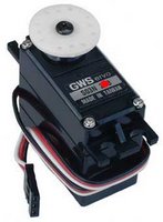
This is an example how to control servos with 8051 by using PWM. The schematic is shown below. I use P1.4 (CEX1) to control the left servo and P1.2 (CEX2) to control the right servo. Here, I use GWS servo motor model S03T STD. I need three states of duty cycle:
  • 20 ms to Stop the servo
  • 1 ms to Rotate Clockwise
  • 2 ms to Rotate Counter-clockwise

Calculation for duty cycle (for XTAL 18.432 MHz with 6 Clock/Machine cycle)
  • Initial PWM Period = 20mS (18.432MHz /6-Cycle Mode)
  • Initial PCA Count From Timer0 Overflow
  • 1 Cycle of Timer0 = (1/18.432MHz)x6 = 0.326 uS
  • Timer0 AutoReload = 240 Cycle = 78.125 uS
  • 1 Cycle PCA = [(1/18.432MHz)x6]x240 = 78.125 uS
  • Period 20mS of PCA = 20ms/78.125us = 256 (CL Reload)
  • CL (20mS) = 256 Cycle Auto Reload
  • Load CCAPxH (1.0mS) = 256-13 = 243 (243,244,...,255 = 13 Cycle)
  • Load CCAPxH (2.0mS) = 255-26 = 230 (230,231,...,255 = 26 Cycle)

Schematic: Control RC Servos motors with 8051 PWM

Datasheet
- P89V51RD2 [pdf]

Source Code (For SDCC) 
pwm_servos.h
test_servos.c

EEPROMs Interfacing

24LC512 is a 64K x 8 (512 Kbit) Serial Electrically Erasable PROM (EEPROMs), from Microchip Technology Inc. (see the product page). It has been developed for advanced, low-power applications such as personal communications and data acquisition. This device also has a page write capability of up to 128 bytes of data.
This device is capable of both random and sequential reads up to the 
512K boundary. Functional address lines allow up to eight devices on the same bus, for up to 4 Mbit address space.
This is an example how to interface 24XXX EEPROMs with 8051. I use SDCC as C Compiler. My schematic is shown below.
Schematic: 8051 interface to 24XXX EEPROMs
Datasheet
- 24LC512 [pdf]
Source Code (For SDCC) 
24xx512.h
test_eeprom.c
Note: require lcd.h and i2c.h

I²C Bus Interfacing

I²C bus (Inter-Integrated Circuit) is a bidirectional, half duplex, two-wire, synchoronous bus, originally designed for interconnection over short distances within a piece of equipment. The I2C bus uses two lines called Serial Clock Line (SCL) and Serial Data Lines (SDA). Both lines are pulled high via a resistor (Rpu) as shown in Figure below. The bus is defined by Philips, see more details.
Three speed modes are specified: Standard; 100kbps [Bits per Second], Fast mode; 400kbps, High speed mode 3.4Mbps. I2C, due to its two-wire nature (one clock, one data) can only communicate half-duplex. The maximum bus capacitance is 400pF, which sets the maximum number of devices on the bus and the maximum line length.
The interface uses 8 bit long bytes, MSB (Most Significant Bit) first, with each device having a unique address. Any device may be a Transmitter or Receiver, and a Master or Slave. The Slave is any device addressed by the Master. A system may have more than one Master, although only one may me active at any time.
Data and clock are sent from the Master: valid while the clock line is high. The link may have multiple Masters and Slaves on the bus, but only one Master may be active at any one time. Slaves may receive or transmit data to the master.

This is an example how to interface I²C with 8051. I use SDCC as C Compiler. My schematic is shown below. I set P2.6 as SCL and P2.7 as SDA.


Schematic: I²C Bus
Datasheet 
I²C-Bus Specification [pdf]

Source Code (For SDCC) 
i2c.h

Note: see DS1307 and 24LC512 for applications


Related Links
Philips I²C Bus 
I2C (Inter-Integrated Circuit) Bus Technical Overview and Frequently Asked Questions (FAQ)
I²C Bus and Access Bus
http://www.i2c-bus.org/

Real Time Clock Interfacing

DS1307, a 64 x 8, Serial, I2C Real-Time Clock, is a low-power, full binary-coded decimal (BCD) clock/calendar plus 56 bytes of NV SRAM. Address and data are transferred serially through an I2C, bidirectional bus. The clock/calendar provides seconds, minutes, 
hours, day, date, month, and year information. It a product of Maxim/Dallas Semiconductor, see the product page.
This is an example how to interface DS1307 with 8051. I use SDCC as C Compiler. My schematic is shown below.
Schematic: 8051 interface to DS1307
Datasheet
- DS1307 [pdf]
Source Code (For SDCC) 
ds1307.h
test_ds1307.c

Note: require lcd.h and i2c.h

Analog-to-Digital Interfacing

The ADS7841 is a 4-channel, 12-bit sampling Analog-to-Digital Converter (ADC) with a synchronous serial interface. The resolution is programmable to either 8 bits or 12 bits. It is a product of Burr-Brown form Texas Instrument, see the product page.
This ADC give the 12-bit Binary Code Decimal (BCD) output value therefore the maximum value is 999 integer. If we want to convert this value to the real value, we must divide this value by 4096 (12-bit) and multiply by the maximum real ouput. Suppose the real maximum of output is 5V, the ratio should be 5/4096 = 0.00122. We can use 0.00122 multiply the output from ADS7841 to get the real ouput value.
This is an example how to interface ADS7841 with 8051. I use SDCC as C Compiler. My schematic is shown below. I still do not convert to the real value so my variables are integer.

Schematic: 8051 interface to ADS7841
Datasheet
- ADS7841 [pdf]

Source Code (For SDCC) 
ads7841.h
test_ads7841.c

Note: require lcd.h


Related Links
ADS7841 Products Page

Distance Measurement Sensor


GP2Y0A21YK is General Purpose Type Distance Measuring Sensors from Sharp. (see the product page). Sharp Infrared (IR) radiation Distance Measuring Sensor use Infrared signal to measure object distance from 10 to 80 cm with analog output.
Features
  1. Less influence on the color of reflective objects, reflectivity
  2. Line-up of distance output/distance judgement type
    Distance output type (analog voltage) : GP2Y0A21YK
    Detecting distance : 10 to 80cm
    Distance judgement type : GP2Y0D21YK
    Judgement distance : 24cm
    (Adjustable within the range of 10 to 80cm [Optionally available])
  3. External control circuit is unnecessary
  4. Low cost
Applications
  1. TVs
  2. Personal computers
  3. Cars
  4. Copiers
  5. Robots
The output of this sensor is analog therefore it need Analog to Digital Converter (ADC) to interface the 8051. I use ads7841 as ADC (see this article).
The graph of Analog voltage output versus distance to reflective object are shown in Fig.1. When I plot Analog voltage output versus inverse number distance, I found the linear relation shown in Fig.2.

Fig. 1 Analog voltage output (V) versus distance to reflective object (cm).


Fig. 2 Analog voltage output (V) versus inverse number distance (1/cm).
The linear equation is y = 20.99x + 0.19, where y is voltage output and x invert distance. Notice that the voltage output I can trust are about 0.4 to 2.8 V.
This is an example code how to interface the distance sensor to 8051. I use SDCC as C Compiler.

  #include <8051.h>

 #include "ads7841.h"

  void main()

 {

     float x,y; // Distance and Analog voltage output

     y = analog(0); // Read volt out if the sensor connect to channel 0 of ADS7841

     y = 0.00122*y; // Convert BCD to DEC by multiply voltage by 5/4096

     if ( (y > 0.4) && (y < 2.8) ) {

        x = (y-0.19)/20.99; // Solve the linear equation

        x = 1/x; // Inverse back get distance in cm.

    }

 }


Source:
test_irsensor.c
characteristic.txt (For plot with Spreadsheet)

Related Links

GP2Y0A21YK/GP2Y0D21YK Datasheet
Analog to Digital (ADS7841) Interfacing

Introduction to SDCC: Small Device C Compiler

SDCC is a Freeware, retargettable, optimizing ANSI - C compiler that targets the Intel 8051, Maxim 80DS390, Zilog Z80 and the Motorola 68HC08 based MCUs. Work is in progress on supporting the Microchip PIC16 and PIC18 series. AVR and gbz80 ports are no longer maintained. The entire source code for the compiler is distributed under GPL.
Some of the features include:
  • ASXXXX and ASLINK, a Freeware, retargettable assembler and linker.
  • extensive MCU specific language extensions, allowing effective use of the underlying hardware.
  • a host of standard optimizations such as global sub expression elimination, loop optimizations (loop invariant, strength reduction of induction variables and loop reversing ), constant folding and propagation, copy propagation, dead code elimination and jump tables for 'switch' statements.
  • MCU specific optimisations, including a global register allocator.
  • adaptable MCU specific backend that should be well suited for other 8 bit MCUs
  • independent rule based peep hole optimizer.
  • a full range of data types: char (8 bits, 1 byte), short (16 bits, 2 bytes), int (16 bits, 2 bytes), long (32 bit, 4 bytes) and float (4 byte IEEE).
  • the ability to add inline assembler code anywhere in a function.
  • the ability to report on the complexity of a function to help decide what should be re-written in assembler.
  • a good selection of automated regression tests.
SDCC also comes with the source level debugger SDCDB, using the current version of Daniel's s51 simulator. (Currently not available on Win32 platforms).
SDCC was written by Sandeep Dutta and released under a GPL license. Since its initial release there have been numerous bug fixes and improvements. As of December 1999, the code was moved to SourceForge where all the "users turned developers" can access the same source tree. SDCC is constantly being updated with all the users' and developers' input.
SDCC Homepage
http://sdcc.sourceforge.net/

Understanding Processor Architecture: Machine and Assembly Language

The processor understands only the machine language, whose instructions consist  of strings of 1s and 0s. Machine language is closely related to the assembly language. We prefer to use the assembly language rather than the machine language. Programming in the assembly language also requires knowledge about the processor architecture.

Assembly language programming is referred to low-level programming because each assembly language instruction performs a much lower-level task compared to an instruction in a high-level language. Assembly language instructions are processor specification dependents. For example, a program written in the Intel assembly language cannot be executed on the PowerPC processor.

Here are some IA-32 assembly language examples:

inc result
mov class_size, 45
and mask1, 128
add marks, 10

The first instruction increments the variable result. This assembly language instruction is equivalent to

result++;

in C. The second instruction initializes class_size to 45. The equivalent statement in C is

class_size = 45;

The third instruction performs the bitwise and operation on mask1 and can be expressed in C as

mask1 = mask1 & 128;

The last instruction updates marks by adding 10. In C, this is equivalent to

marks = marks + 10;

We can translate the assembly language instructions to the equivalent machine language instructions. Machine language instructions are written in the hexadecimal number system. Here are some IA-32 machine language examples:

Assembly


Operation


Machine language (in hex)


nop

No operation90

inc result

IncrementFF060A00

mov class_size, 45

CopyC7060C002D00

and mask, 128

Logical and80260E0080

add marks, 10

Integer addition83060F000A


References
  • Guide to RISC Processors for Programmers and Engineers by Sivarama P. Dandamudi, Springer (2005), ISBN 0-387-21017-2.